Jonathan Pounsett Posted June 26, 2022 Share Posted June 26, 2022 Everything on my car is wired up and working correctly with one exception - the alternator charge warning light. I’ve never been a big fan of auto electrics and this is driving me made. I know what most things do and can follow a line on a wiring diagram but trying to get access to stuff tucked up under the dashboard with your head in the foot well isn’t my idea of fun and the pains in my back are crippling. The quick question is how do I make the charge light work correctly? I’ll try and provide some background but this will possibly be more confusing. I think the problems I have all relate to the omission of the voltage regulator or are at least associated with it. The Rover alternator is a smart alternator (built-in regulator) so I thought it was simply a case of connecting the D+ pole from the alternator to the blue/white wire that used to connect to the voltage regulator. That doesn’t work! I’ve attached a simplified diagram and you can see I only have two wires to play with or three if you include the wire from the alternator; Blue/white - was connected to the voltage regulator, now not connected to anything, Brown/white - from heated rear window switch, now not connected to anything, Green/white - a new wire from D+ pole on the alternator. With none of these wires connected the warning light does NOT light up when I switch on the ignition but it DOES illuminate if I turn on the heated rear window. As there is no connection from the alternator no warning light would be triggered. If I connect the blue/white to the D+, the warning light comes on when the ignition is switched on but remains on when the engine is started. I’ve tested the output from the alternator and this is all good. I’ll be a happy man if anyone with expertise in this area could point me in the right direction. Quote Link to comment Share on other sites More sharing options...
Jonathan Pounsett Posted June 29, 2022 Author Share Posted June 29, 2022 Anybody able to help - Not had any replies ! Quote Link to comment Share on other sites More sharing options...
Jessopia74 Posted June 29, 2022 Share Posted June 29, 2022 Get me a better pic of the rear of the alternator please in good light. You might need a link, but I can see . Aalso diagram is a little confusing I guess as it seems to look on first glance like you an external regulator, but very doubtful from the terminals on alternator. 1 Quote Link to comment Share on other sites More sharing options...
611 Posted June 29, 2022 Share Posted June 29, 2022 Not sure if its similar to the A but i have one with no regulator and i think its the blue and white that comes off the D+ and it needs to be the terminal not the spade connector. As i had mine on the spade which looked like it was the D+ but it the terminal next to it that is actually the D+ This is the back of mine. Andy 1 Quote Link to comment Share on other sites More sharing options...
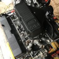
Jonathan Pounsett Posted June 30, 2022 Author Share Posted June 30, 2022 (edited) 14 hours ago, Jessopia74 said: Get me a better pic of the rear of the alternator please in good light. You might need a link, but I can see . Aalso diagram is a little confusing I guess as it seems to look on first glance like you an external regulator, but very doubtful from the terminals on alternator. The diagram is a simplified extract from Haynes showing the voltage regulator omitted. I should have stressed that the Manta alternator has be swapped to the Range Rover P38 one. It’s a Marelli A1271M 14v 100A unit. The alternator outputs are; Post. With the ignition off. with ignition on. With the engine running B+. 12.8v 12.7v. 14.1v D+. 0v. 0.65v (*). 2.4v W. 0v. 0v. 7v (*) The wire from the D+ post is not currently connected to anything so I assume this voltage must be via an internal connection? The manta voltage regulator’s range is 13.9 - 14.8v so I would have expected 14.1v to be sufficient to extinguish the charge light. This is the clearest photo of the alternator I can find; 13 hours ago, 611 said: Not sure if its similar to the A but i have one with no regulator and i think its the blue and white that comes off the D+ and it needs to be the terminal not the spade connector. As i had mine on the spade which looked like it was the D+ but it the terminal next to it that is actually the D+ This is the back of mine. Andy That’s what I’ve tried and through a process of elimination it can’t be anything else. Does you’re blue/white wire go to the rear window relay ( as on a B ) or does it go somewhere else? Edited June 30, 2022 by Jonathan Pounsett Brackets added Quote Link to comment Share on other sites More sharing options...
Jessopia74 Posted June 30, 2022 Share Posted June 30, 2022 (edited) 3 hours ago, Jonathan Pounsett said: The diagram is a simplified extract from Haynes showing the voltage regulator omitted. I should have stressed that the Manta alternator has be swapped to the Range Rover P38 one. It’s a Marelli A1271M 14v 100A unit. The alternator outputs are; Post. With the ignition off. with ignition on. With the engine running B+. 12.8v 12.7v. 14.1v D+. 0v. 0.65v (*). 2.4v W. 0v. 0v. 7v (*) The wire from the D+ post is not currently connected to anything so I assume this voltage must be via an internal connection? The manta voltage regulator’s range is 13.9 - 14.8v so I would have expected 14.1v to be sufficient to extinguish the charge light. This is the clearest photo of the alternator I can find; That’s what I’ve tried and through a process of elimination it can’t be anything else. Does you’re blue/white wire go to the rear window relay ( as on a B ) or does it go somewhere else? That should simply be D+ to the bulb -ve side (bulb needs +ve from ignition or battery etc) . It goes low when alternator is not output and high when it is. (+ve out) . If you drop it off the relay for now, you can hook a bulb between D+ and will light up when not running as it earths the bulb, and then goes +ve output when running. the reason why it’s on the relay, is it works inverse if the bulb. It uses the switch from low(-ve) when not running to high (+ve) to engage relay so that the rear screen circuit can complete. Edit - added the most simplest way to check using your pic with a test lamp (bulb type). You can even use the B+ term on batt or the terminal on the alternator since it’s directly connected to the alternator. Just make sure the Alternator body has a good earth. You can jump a wire if unsure to prove it. Edited June 30, 2022 by Jessopia74 1 Quote Link to comment Share on other sites More sharing options...
Jonathan Pounsett Posted June 30, 2022 Author Share Posted June 30, 2022 56 minutes ago, Jessopia74 said: That should simply be D+ to the bulb -ve side (bulb needs +ve from ignition or battery etc) . It goes low when alternator is not output and high when it is. (+ve out) . If you drop it off the relay for now, you can hook a bulb between D+ and will light up when not running as it earths the bulb, and then goes +ve output when running. the reason why it’s on the relay, is it works inverse if the bulb. It uses the switch from low(-ve) when not running to high (+ve) to engage relay so that the rear screen circuit can complete. Edit - added the most simplest way to check using your pic with a test lamp (bulb type). You can even use the B+ term on batt or the terminal on the alternator since it’s directly connected to the alternator. Just make sure the Alternator body has a good earth. You can jump a wire if unsure to prove it. Thanks @Jessopia74, I will try tonight 🤞 1 Quote Link to comment Share on other sites More sharing options...
611 Posted June 30, 2022 Share Posted June 30, 2022 I will check mine but do check the earth as mine had 2 issues, one the earth was crap and two i had it on the spade and not the terminal! Quote Link to comment Share on other sites More sharing options...
Jonathan Pounsett Posted July 2, 2022 Author Share Posted July 2, 2022 I haven’t solved the problem but I have identified a fault. For the charge light to illuminate you have a positive supply from the ignition which runs through the alternator to earth. When the alternator starts to do it’s job a positive current is generated - the circuit is corrupted and the light goes out. The fault I have is that the D+ terminal measures 0.65 volts when the ignition is switched on but I think this should be 0 volts! Sounds like @611 may be right and I have a bad earth. Quote Link to comment Share on other sites More sharing options...
611 Posted July 2, 2022 Share Posted July 2, 2022 2 hours ago, Jonathan Pounsett said: I haven’t solved the problem but I have identified a fault. For the charge light to illuminate you have a positive supply from the ignition which runs through the alternator to earth. When the alternator starts to do it’s job a positive current is generated - the circuit is corrupted and the light goes out. The fault I have is that the D+ terminal measures 0.65 volts when the ignition is switched on but I think this should be 0 volts! Sounds like @611 may be right and I have a bad earth. Definitely worth investigating as i thought my earth was good, but when i did a test it turned out it was a bit intermittent and once i swapped it for a new strap it cured it. At least if you get that so you know its spot on its one less thing it can be 🙂 Quote Link to comment Share on other sites More sharing options...
Jonathan Pounsett Posted July 2, 2022 Author Share Posted July 2, 2022 (edited) One step forward…… In an effort to keep the wiring neat I had packaged together the charge light wire with the main battery/starter motor wire and this was creating an induced current in the smaller wire 🤦♂️. The charge light is fixed. One step back…… This has somehow created a rogue ignition circuit and the engine won’t switch of unless I disconnect the charge light wire! Kin hell 🤬 Edited July 2, 2022 by Jonathan Pounsett Quote Link to comment Share on other sites More sharing options...
611 Posted July 2, 2022 Share Posted July 2, 2022 2 hours ago, Jonathan Pounsett said: One step forward…… In an effort to keep the wiring neat I had packaged together the charge light wire with the main battery/starter motor wire and this was creating an induced current in the smaller wire 🤦♂️. The charge light is fixed. One step back…… This has somehow created a rogue ignition circuit and the engine won’t switch of unless I disconnect the charge light wire! Kin hell 🤬 Always the way 🙂 Quote Link to comment Share on other sites More sharing options...
Jessopia74 Posted July 3, 2022 Share Posted July 3, 2022 16 hours ago, Jonathan Pounsett said: One step forward…… In an effort to keep the wiring neat I had packaged together the charge light wire with the main battery/starter motor wire and this was creating an induced current in the smaller wire 🤦♂️. The charge light is fixed. One step back…… This has somehow created a rogue ignition circuit and the engine won’t switch of unless I disconnect the charge light wire! Kin hell 🤬 Should be diode in the cluster on the lamp that prevents this. 1 Quote Link to comment Share on other sites More sharing options...
Jonathan Pounsett Posted July 3, 2022 Author Share Posted July 3, 2022 4 hours ago, Jessopia74 said: Should be diode in the cluster on the lamp that prevents this. Is it likely that I’ve fried the diode with all my experimentation and is it going to fail again? Is it something I can replace and does anyone know the part number for a replacement? Quote Link to comment Share on other sites More sharing options...
Jessopia74 Posted July 3, 2022 Share Posted July 3, 2022 It will be on the flexible PCB, iirc they are a surface mounted type, but old style so should be able to be replaced with an equivalent if your solder skills are up to the job? 1 Quote Link to comment Share on other sites More sharing options...
cam.in.head Posted July 4, 2022 Share Posted July 4, 2022 if we are talking a standard manta b/ cav dash ive never seen one with a diode on it.the 12v feed from the ign switch to instruments would feed oil,bat and handbrake lamps and the tacho and voltage regulator supply. the bat light then simply runs to the IND terminal on a standard delco alternator or D+ on the bosch. not helping here much due to your non standard alternator but if it has an internal regulator then it should wire up / work the same ? and also with the factory wiring the waring light wire and power cable are all taped up together with no issues. have you doene anything different withthe heated rear window relay or replaced it with awrong type ? 1 Quote Link to comment Share on other sites More sharing options...
Jonathan Pounsett Posted July 4, 2022 Author Share Posted July 4, 2022 8 minutes ago, cam.in.head said: if we are talking a standard manta b/ cav dash ive never seen one with a diode on it.the 12v feed from the ign switch to instruments would feed oil,bat and handbrake lamps and the tacho and voltage regulator supply. the bat light then simply runs to the IND terminal on a standard delco alternator or D+ on the bosch. not helping here much due to your non standard alternator but if it has an internal regulator then it should wire up / work the same ? Do you know what voltage I should see at the IND or D+ terminal on standard Manta alternators with the engine running? I’m confused because all the wiring in the cabin and dash is original and unmolested and I’ve connected this to the D+ terminal on the Marelli A1271M alternator. Without this connection the ignition, and everything else for that matter, works fine but with it connected the ignition switch doesn’t kill the engine. Quote Link to comment Share on other sites More sharing options...
cam.in.head Posted July 4, 2022 Share Posted July 4, 2022 what happens if you remove the heated rear window relay ? i can measure the voltage output on mine for you if you want but mine are std bosch alterators i can measure the voltage output on mine for you if you want but mine are std bosch alterators but to be honest (unless the alternator is faulty) it just sounds like youhave the lamp wire on the wrong terminal Quote Link to comment Share on other sites More sharing options...
cam.in.head Posted July 4, 2022 Share Posted July 4, 2022 (edited) right just done some measurements for you. engine off,ignition off. main terminal battery voltage 12.6v d+ terminal .0002v engine off but ignition turned on .light lit. main terminal voltage 12.0v d+ terminal 2.7v ( this should be as near to zero as possible but wont be due to internal resistance of the alternator,regulator and any wiring .(other car neasures 2.1v)both cars work fine .no issues. engine running light off main terminal 14.2v d+ terminal 14.2v the fact that your car stays running with the wire connected suggests that either 12v is going up the wire when it shouldnt ,connected wrong or these an issue with the hrw relay. Edited July 4, 2022 by cam.in.head Quote Link to comment Share on other sites More sharing options...
Jonathan Pounsett Posted July 4, 2022 Author Share Posted July 4, 2022 The situation is the same with the HRW relay removed. The blue/white wires from the alternator and the warning bulb join at the same spade connector so the relay wouldn’t affect this. I’ve got a spare dash so I’ll try that and see if the problem persists. I will also check the bulb connections. I’m using led bulbs which I didn’t realise have polarity and the “d” in led is for “Diode” so @Jessopia74 may be right. 1 Quote Link to comment Share on other sites More sharing options...
Jonathan Pounsett Posted July 4, 2022 Author Share Posted July 4, 2022 The leds I put in were for dashboard lights so irrelevant. Turns out I have a few other dashboards to try. The warning light came on with the ignition on first one I tried and went off with the engine running and the ignition shut off the engine. Great problem solved…. well no not quite. On second try no light (the bulb is good). The second dash is a slightly different configuration and the hazard warning light is off when the ignition is on and comes on when the engine is running. The ignition doesn’t kill the engine. I opened up one of the spares dashes and guess what?…. there is a diode on the back of the gauge. I don’t know what the other components are or what they do. Quote Link to comment Share on other sites More sharing options...
Jessopia74 Posted July 4, 2022 Share Posted July 4, 2022 9 hours ago, Jonathan Pounsett said: The situation is the same with the HRW relay removed. The blue/white wires from the alternator and the warning bulb join at the same spade connector so the relay wouldn’t affect this. I’ve got a spare dash so I’ll try that and see if the problem persists. I will also check the bulb connections. I’m using led bulbs which I didn’t realise have polarity and the “d” in led is for “Diode” so @Jessopia74 may be right. Ah! You also need a resistor with the led in that case mate. Quote Link to comment Share on other sites More sharing options...
Jonathan Pounsett Posted July 5, 2022 Author Share Posted July 5, 2022 Auto electrician coming out on Friday. 1 Quote Link to comment Share on other sites More sharing options...
Jessopia74 Posted July 5, 2022 Share Posted July 5, 2022 1 hour ago, Jonathan Pounsett said: Auto electrician coming out on Friday. Think your close to getting it set, but getting. Chap to help with the last bit will be worth it than burning our part of the loom 👍 1 Quote Link to comment Share on other sites More sharing options...
cam.in.head Posted July 5, 2022 Share Posted July 5, 2022 you arent swapping non tacho dashes and 6 dial dashes around are you. ? you probably know or have found out that they are not interchangeable without rewiring the main dash connectors . pins / wires are not in the same place . hopefully the electrician should be able to sort it for you as its always hard when the cars not in front of you. the guage you showed looks like the voltmeter and the components on the back are simply to run that particular guage and adjust it . and obviously thats only on the 6 dial dash anyway Quote Link to comment Share on other sites More sharing options...

Recommended Posts
Join the conversation
You can post now and register later. If you have an account, sign in now to post with your account.